Phone:400-8765-198
Cell phone:


Phone:400-8765-198
Cell phone:


Brief introduction
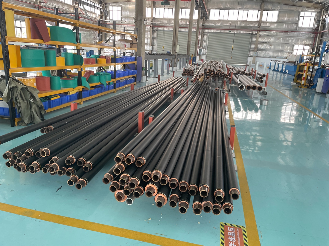
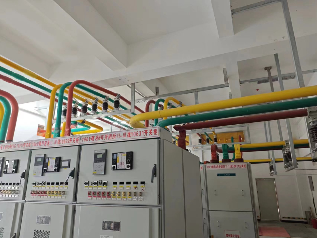
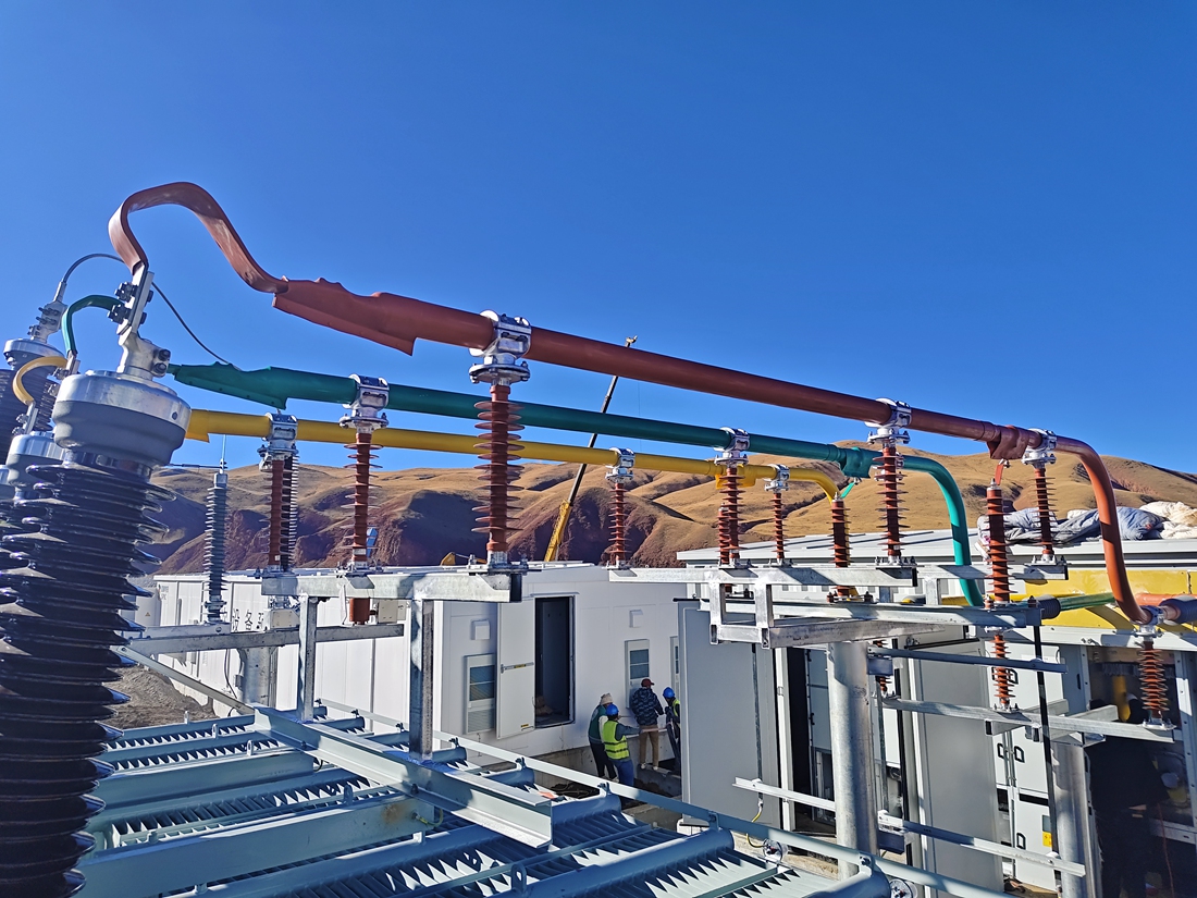
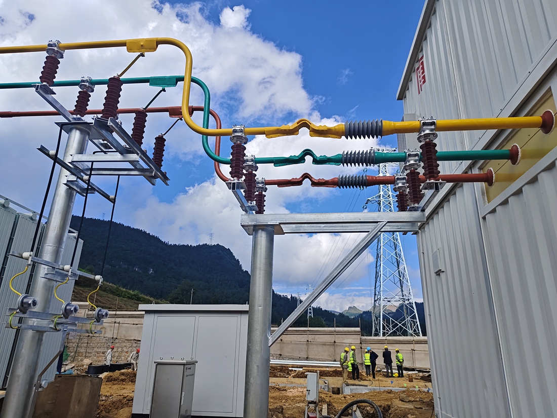
The extruded solid insulation tube busbar is a technology borrowed from cable insulation. Using a large extrusion machine, EPDM rubber and semiconducting rubber are extruded onto the surface of copper tube conductors in one go. The interface between the inner shielding layer, main insulation layer, and outer shielding layer insulation is tightly adhered without gaps, greatly improving the performance of the insulated tubular busbar. This three-layer co extruded insulated busbar not only has strong electrical performance, but also uses prefabricated cold shrink silicone rubber insulation structural components for the middle joint of the busbar, and a stress cone structured cold shrink silicone rubber umbrella skirt for the end. The connection and installation process is basically the same as that of the cable, ensuring the on-site installation quality of the insulated busbar. The extruded tubular bus has high withstand voltage value, basically zero partial discharge, strong anti-aging ability and long service life. All indicators have reached a qualitative leap compared with the wrapped insulated tubular bus, and the overall performance has been greatly improved.
The main process flow of extruded process tube busbar is:
① Copper tube conductor cutting and surface cleaning - ② Three layer insulation co extruded onto the copper tube surface - ③ High temperature vulcanization of the tube insulation - ④ Grinding of the tube end - ⑤ Machining of the tube - ⑥ Tube bending - ⑦ Production of the tube grounding screen and protective layer - ⑧ Factory testing - ⑨ Product packaging - ⑩ Delivery to the site - ⑪ Installation of the tube on site.
Several key points of extrusion tube mother equipment and production process
1. The minimum requirement for the extrusion workshop is 2000 square meters or more, with a clean workshop with constant temperature and humidity, a professional laboratory, and testing equipment.
2. The tube mother extrusion equipment should have the ability of three-layer co extrusion, that is, a total of three layers of insulation can be extruded at once from the inside out, including the innermost "conductor shielding layer" (semiconductor layer), the middle "main insulation layer" (EPDM rubber, silicone rubber, polyethylene), and the outer "insulation shielding layer". If only one or two layers can be extruded, it is considered unqualified.
3. To ensure the performance of the tube mother extrusion equipment, its power can be considered, and the total power should not be less than 240kW.
4. The insulation layer thickness of 10kV products is usually 8mm, and the insulation layer thickness of 35kV products is not less than 17mm, with a negative tolerance of no more than 1mm.
5. A high-power vulcanization tank is required, with a working pressure of not less than 0.8MPa and a temperature of not less than 180 ℃. Failure to meet these requirements may result in incomplete vulcanization and unstable insulation effect. The power of the vulcanization tank should not be less than 180kW.
6. The grounding shield of the busbar should be made of aluminum foil or copper foil, and the grounding wire should be led out with a copper wire of not less than 25mm2. The production of grounding shielding should be carried out in a clean workshop with constant temperature (25 ℃) and humidity (relative humidity not exceeding 50%), otherwise it will affect the insulation effect.
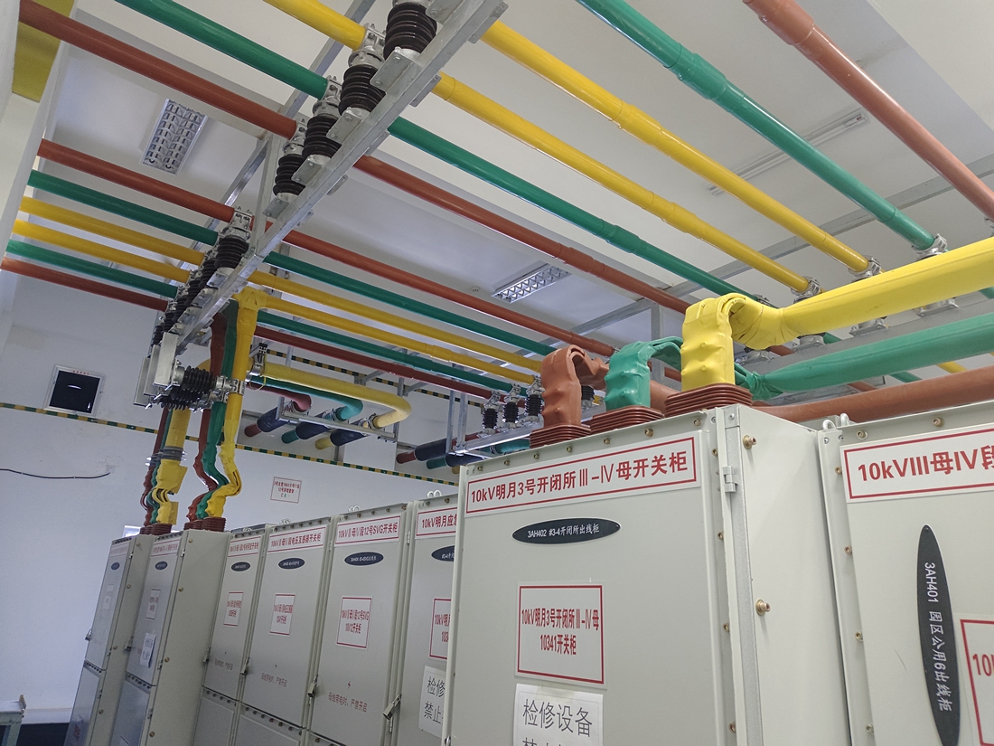
7. It is recommended to use prefabricated silicone rubber cold shrink parts for the insulation of the intermediate joint of the tube busbar, and it is not recommended to use shielding tubes (due to sealing issues, which can easily cause water leakage, cracking, etc.). The two ends of the cold shrink joint have stress cone structures, which are connected to the stress cone structure of the tube busbar joint to ensure that the surface potential of the entire conductor is zero.
8. The tube terminal should also be equipped with a cold shrink umbrella skirt, which, like the prefabricated intermediate joint, needs to have a stress cone structure to ensure the reliability of the end insulation.
9. Manufacturers must have a professional non partial discharge shielding laboratory, equipped with power frequency withstand voltage equipment above 120kV, partial discharge testers (must be connected to non partial discharge transformers), dielectric loss testers, and contact resistance testers. Before leaving the factory, a 5-minute power frequency withstand voltage test, partial discharge test (under 1.05 times the rated voltage, partial discharge not exceeding 7pc), and dielectric loss test should be conducted.
Hotline : 400-8765-198
Cell phone:
Welcome customers to visit our factory for inspection and negotiation!
Address:No. 86 Xingcheng Avenue, Hannan District, Wuhan City, Hubei Province